

Graco Diaphragm Pump HUSKY 2150 Model DF3525
Packing and shipping
|
Packaging Regulation : |
Wooden box |
|
Delivery time : |
7~14 days(About) |
|
Conditions : |
New and Genuine |
How do you order?
A&S makes ordering GET Parts easy. Simply send a mail to Us. Instead of searching online and guessing which parts you need, our team will make sure you get the correct parts. We process and deliver your order fast, and always at a competitive price. Enjoy 5-star service!
1.IDENTIFY
Determine the parts you need. To ensure the correct parts are quoted, it's best to have the machine make and model, along with part numbers and photos of the nameplate if possible. Our team of professionals are here to help ensure you get the correct parts that fit and work the first time. Our sales team can also survey and help identify the parts you may need. Please email us to get started!
2.ORDER
Our professional internal sales teams and strong supply chain system will assist you to identify the right parts, and can recommend the most cost-effective solution for you. Our team of professionals will process your order, and ensure your order is correct the first time. With over 15 years in the business, we remove the guesswork and always deliver.
3.DELIVER
We'll ship or deliver your products as required, to your nominated location. If you're also located elsewhere, we'll identify the best shipping options for both price and delivery time. Email us now!
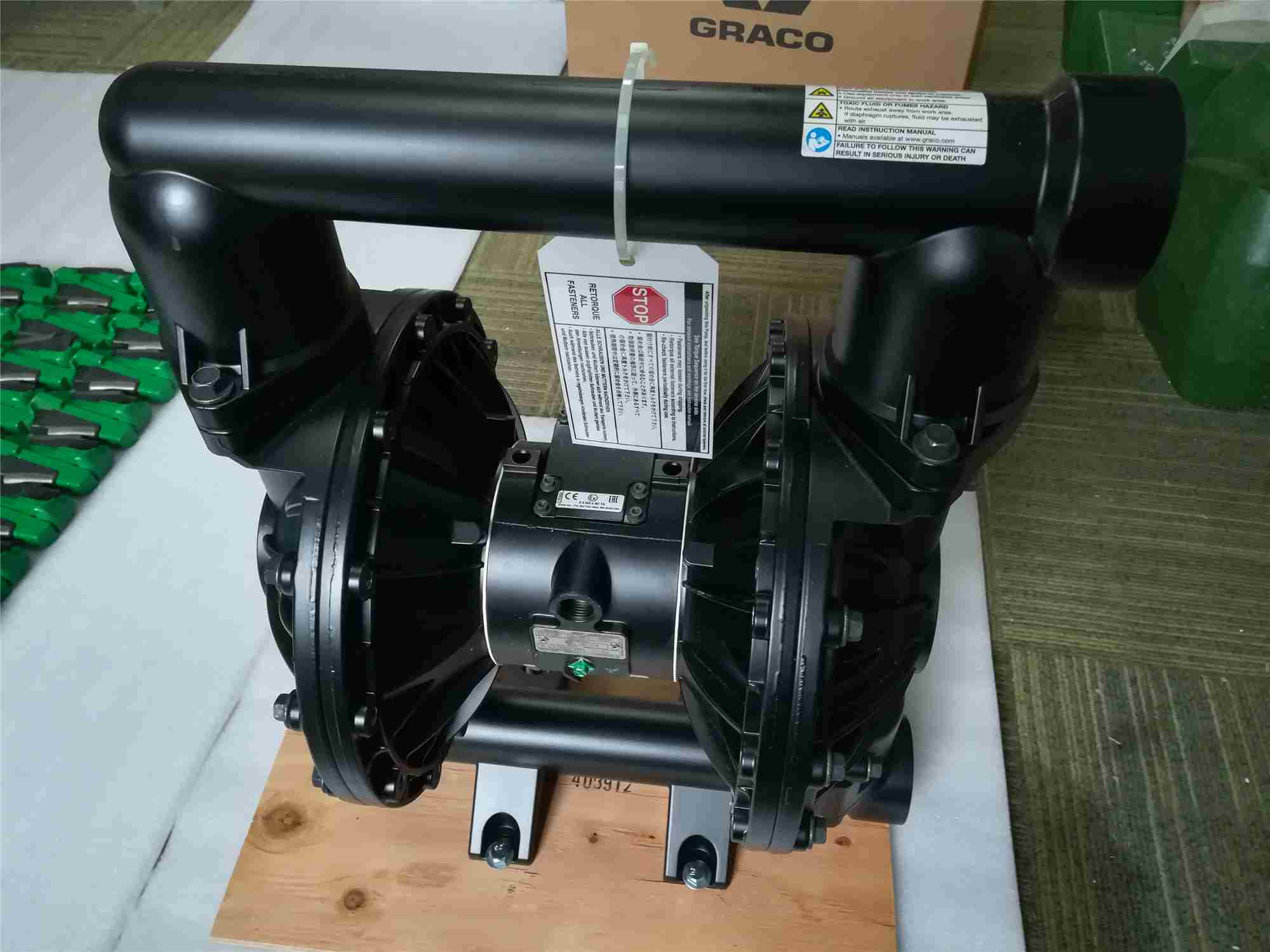
HUSKY 2150 Model DF3525-A0217092
Husky 2150 Air-Operated Diaphragm Pumps
See Models on page 2 for a list of pump models and descriptions.
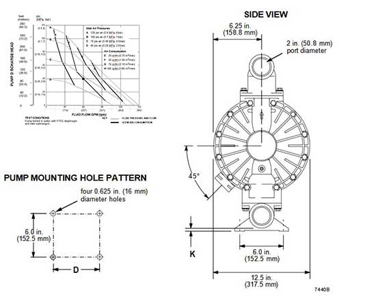
120 psi (0.8 MPa, 8 bar) Maximum Fluid Working Pressure 120 psi (0.8 MPa, 8 bar) Maximum Air Input Pressure
Patent No.
CN ZL94102643.4 FR 9408894
JA 3517270
US 5,368,452
Important Safety Instructions
Read all warnings and instructions in the manual. Save these instructions.
Models
|
Model No. |
Description |
|
*DF3 |
Aluminum Pumps |
|
*DG3 |
Aluminum Pumps, Remote |
|
*DFH |
Aluminum Extended Pump |
|
*DGH |
Aluminum Extended Pump, Remote |
|
*DF4 |
Stainless Steel Pumps |
|
*DG4 |
Stainless Steel Pumps, Remote |
|
*DF6 |
Ductile Iron Pumps |
|
*DG6 |
Ductile Iron Pumps, Remote |
|
*DFC |
Aluminum BSPT Pumps |
|
*DGC |
Aluminum BSPT Pumps, Remote |
|
*DFD |
Stainless Steel BSPT Pumps |
|
*DGD |
Stainless Steel BSPT Pumps, Remote |
|
*DFF |
Ductile Iron BSPT Pumps |
|
*DGF |
Ductile Iron BSPT Pumps, Remote |
|
*DFG |
Aluminum BSPT Extended Pump |
|
*DGG |
Aluminum BSPT Extended Pump, Remote |
|
*DV4 |
Stainless Steel Plus Pumps |
|
*DVD |
Stainless Steel BSPT Plus Pumps |
|
232503 |
Privatea€“Label Aluminum 2150 Pump (See page 22.) |
|
24B782 |
Aluminum Pump with overmolded diaphragms |
|
24B783 |
Stainless Steel Plus Pump with overmolded diaphragms |
|
24B801 |
Stainless Steel Pump with overmolded diaphragms |
*NOTE: Refer to the Pump Matrix on page 22 to determine the Model No. of your pump.
NOTE: Plus Models include stainless steel center sections.
Symbols
Warning Symbol
WARNING
This symbol alerts you to the possibility of serious injury or death if you do not follow the instructions.
Caution Symbol
CAUTION
This symbol alerts you to the possibility of damage to or destruction of equipment if you do not follow the instructions.
WARNING
EQUIPMENT MISUSE HAZARD
Any misuse of the equipment or accessories, such as overpressurizing, modifying parts, using incompatible chemicals and fluids, or using worn or damaged parts, can cause them to rupture and result in splashing in the eyes or on the skin, other serious injury, or fire, explosion or property dam- age.
•This equipment is for professional use only. Observe all warnings. Read and understand all instruction manuals, warning labels, and tags before operating the equipment.
•Never alter or modify any part of this equipment; doing so could cause it to malfunction. Use only genuine Graco parts and accessories.
•Check all equipment regularly and repair or replace worn or damaged parts immediately.
•Never exceed the recommended working pressure or the maximum air inlet pressure stated on your pump or in the Technical Data on page 32.
•Do not exceed the maximum working pressure of the lowest rated component in your system. This equipment has a 120 psi (0.8 MPa, 8 bar) maximum working pressure at 120 psi (0.8 MPa, 8 bar) maximum incoming air pressure.
•Be sure that all fluids and solvents used are chemically compatible with the wetted parts shown in the Technical Data on page 32. Always read the manufacturer’s literature before using fluid or solvent in the pump.
•Never move or lift a pump under pressure. If dropped, the fluid section may rupture. Always follow the Pressure Relief Procedure on page 10 before moving or lifting the pump. The pump is very heavy. If it must be moved, have two people lift the pump by grasping the outlet manifold securely.
HAZARDOUS FLUIDS
Improper handling of hazardous fluids or inhaling toxic vapors can cause extremely serious injury, even death, due to splashing in the eyes, ingestion, or bodily contamination. Observe all the follow- ing precautions when handling known or potentially hazardous fluids.
•Know what fluid you are pumping and its specific hazards. Take precautions to avoid a toxic fluid spill.
•Always wear appropriate clothing and equipment, such as eye protection and breathing appara- tus, to protect yourself.
•Store hazardous fluid in an appropriate, approved container. Dispose of it according to all Local, State and Federal guidelines for hazardous fluids.
•Secure the fluid outlet hose tightly into the receiving container to prevent it from coming loose and improperly draining the fluid.
•Pipe and dispose of the exhaust air safely, away from people, animals, and food handling areas. If the diaphragm fails, the fluid is exhausted along with the air. See Air Exhaust Ventilation on page 9.
FIRE AND EXPLOSION HAZARD
Static electricity is created by the flow of fluid through the pump and hose. If the equipment is not properly grounded, sparking may occur. Sparks can ignite fumes from solvents and the fluid being pumped, dust particles and other flammable substances, whether you are pumping indoors or out- doors, and can cause a fire or explosion and serious injury and property damage.
•To reduce the risk of static sparking, ground the pump and all other equipment used or located in the work area. Check your local electrical code for detailed grounding instructions for your area and type of equipment. Refer to Grounding on page 5.
•If you experience any static sparking or even a slight shock while using this equipment, stop pumping immediately. Check the entire system for proper grounding. Do not use the system again until the problem has been identified and corrected.
•Pipe and dispose of the exhaust air safely, away from all sources of ignition. If the diaphragm fails, the fluid is exhausted along with the air. See Air Exhaust Ventilation on page 9.
•Do not smoke in the work area. Do not operate the equipment near a source of ignition or an open flame, such as a pilot light.
HALOGENATED HYDROCARBON HAZARD
Never use 1,1,1-trichloroethane, methylene chloride, other halogenated hydrocarbon solvents or fluids containing such solvents in Aluminum Pumps. Such use could result in a serious chemical reaction, with the possibility of explosion, which could cause death, serious injury and/or substantial property damage.
Consult your fluid suppliers to ensure that the fluids used are compatible with aluminum parts.
Installation
General Information
•The Typical Installation shown in Fig. 2 is only a
guide for selecting and installing system compo- nents. Contact your Graco distributor or Graco Technical Assistance (see back page) for assis- tance in planning a system to suit your needs.
•Always use Genuine Graco Parts and Accessories.
•Reference numbers and letters in parentheses refer to the callouts in the figures and the parts lists on pages 24 to 25.
HAZARDOUS FLUIDS
To reduce the risk of serious injury, splashing in the eyes or on the skin, and toxic fluid spills, never move or lift a
pump under pressure. If dropped, the fluid section may rupture. Always follow the Pressure Relief Procedure Warning on page 10 before moving or lifting the pump.
•The pump is very heavy. If it must be moved, have two people lift the pump by grasping the outlet manifold (103) securely. See Fig. 3 on page 8.
Tightening Screws Before First Use
Before using the pump for the first time, check and retorque all external fasteners. See Torque Se- quence, page 29. After the first day of operation, retorque the fasteners. Although pump use varies, a general guideline is to retorque fasteners every two months.
Grounding
FIRE AND EXPLOSION HAZARD
This pump must be grounded. Before operating the pump, ground the system as explained below. Also, read the section FIRE AND EXPLOSION HAZARD, on page 4.
To reduce the risk of static sparking, ground the pump and all other equipment used or located in the pumping area. Check your local electrical code for detailed grounding instructions for your area and type of equip- ment. Ground all of this equipment:
•Pump: Connect a ground wire and clamp as shown in Fig. 1. Loosen the grounding screw (W). Insert one end of a 12 ga (1.5 mm²) minimum ground wire
(Y) behind the grounding screw and tighten the screw securely. Connect the clamp end of the ground wire to a true earth ground. Order Part No. 222011 Ground Wire and Clamp.
•Air and fluid hoses: Use only grounded hoses with a maximum of 500 ft (150 m) combined hose length to ensure grounding continuity.
•Air compressor: Follow the manufacturer’s recom- mendations.
•All solvent pails used when flushing: Follow the local code. Use only metal pails, which are conduc- tive. Do not place the pail on a non-conductive surface, such as paper or cardboard, which inter- rupts the grounding continuity.
•Fluid supply container: Follow the local code.
Mountings
CAUTION
The pump exhaust air may contain contaminants. Ventilate to a remote area if the contaminants could affect your fluid supply. See Air Exhaust Ventilation on page 9.
•Be sure the mounting surface can support the weight of the pump, hoses, and accessories, as well as the stress caused during operation.
•For all mountings, be sure the pump is bolted directly to the mounting surface.
•For ease of operation and service, mount the pump so the air valve cover (2), air inlet, and fluid inlet and outlet ports are easily accessible.
•Rubber Foot Mounting Kit 236452 is available to reduce noise and vibration during operation.
Air Line
A bleed-type master air valve (B) is required in your system to relieve air trapped between this valve and the pump. Trapped air can cause the pump to cycle unexpectedly, which could result in serious injury, including splashing in the eyes or on the skin, injury from moving parts, or contamination from hazardous fluids. See Fig. 2.
1.Install the air line accessories as shown in Fig. 2. Mount these accessories on the wall or on a bracket. Be sure the air line supplying the acces- sories is grounded.
- Install an air regulator (C) and gauge to control the fluid pressure. The fluid outlet pressure will be the same as the setting of the air regulator.
b.Locate one bleed-type master air valve (B) close to the pump and use it to relieve trapped air. See the WARNING above. Locate the other master air valve (E) upstream from all air line accessories and use it to isolate them during cleaning and repair.
c.The air line filter (F) removes harmful dirt and moisture from the compressed air supply.
2.Install a grounded, flexible air hose (A) between the accessories and the 1/2 npt(f) pump air inlet (N). See Fig. 2. Use a minimum 1/2” (13 mm) ID air hose. Screw an air line quick disconnect cou- pler (D) onto the end of the air hose (A), and screw the mating fitting into the pump air inlet snugly. Do not connect the coupler (D) to the fitting until you are ready to operate the pump.
Installation of Remote Pilot Air Lines
1.Refer to Parts Drawings. Connect air line to pump as in preceding steps.
2.Connect 1/4 in. O.D. tubing to push type connec- tors (14) on air motor of pump.
NOTE: by replacing the push type connectors, other sizes or types of fittings may be used. The new fittings will require 1/8 in. npt threads.
- Connect remaining ends of tubes to external air signal, such as Graco’s Cycleflo (P/N 195264) or Cycleflo II (P/N 195265) controllers.
Fluid Suction Line
1.Use grounded fluid hoses (G). The pump fluid inlet (R) is 2” npt(f). Screw the fluid fitting into the pump inlet securely.
2.If the fluid inlet pressure to the pump is more than 25% of the outlet working pressure, the ball check valves will not close fast enough, resulting in inefficient pump operation.
3.At inlet fluid pressures greater than 15 psi
(0.1 MPa, 1 bar), diaphragm life will be shortened.
- See the Technical Data on page 32 for maximum suction lift (wet and dry).
Fluid Outlet Line
A fluid drain valve (J) is required to relieve pres- sure in the hose if it is plugged. The drain valve reduces the risk of serious injury, including splash- ing in the eyes or on the skin, or contamination from hazardous fluids when relieving pressure.
Install the valve close to the pump fluid outlet. See Fig. 2.
FLOOR-MOUNT TYPICAL INSTALLATION
KEY
A Air supply hose
B Bleed-type master air valve (required for pump)
C Air regulator
D Air line quick disconnect
E Master air valve (for accessories)
F Air line filter
G Fluid suction hose
H Fluid supply
J Fluid drain valve (required)
K Fluid shutoff valve
L Fluid hose
N 1/2 npt(f) air inlet port
R 2 npt(f) fluid inlet port
S 2 npt(f) fluid outlet port
Y Ground wire (required; see page 5 for installation instructions)
1.Use grounded fluid hoses (L). The pump fluid outlet (S) is 2” npt(f). Screw the fluid fitting into the pump outlet securely.
2.Install a fluid drain valve (J) near the fluid outlet. See the WARNING above.
- Install a shutoff valve (K) in the fluid outlet line.
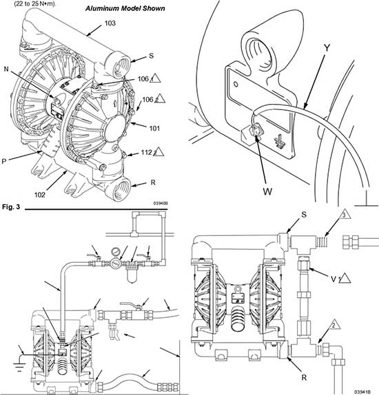
Changing the Orientation of the Fluid Inlet and Outlet Ports
The pump is shipped with the fluid inlet (R) and outlet
(S) ports facing the same direction. See Fig. 3. To change the orientation of the inlet and/or outlet port:
1.Remove the screws (106) holding the inlet (102) and/or outlet (103) manifold to the covers (101).
2.Reverse the manifold and reattach. Install the screws and torque to 120 to 150 in-lb (14 to 17 N•m). on aluminum pumps. Torque to 190–220 in–lb (22–25 N•m) on ductile iron and stainless
steel pumps. See Torque Sequence, page 29.
KEY
N 1/2 npt(f) air inlet port
P Muffler. Air exhaust port is 3/4 npt(f).
R 2 npt(f) fluid inlet port
S 2 npt(f) fluid outlet port
101 Covers
102 Fluid inlet manifold
103 Fluid outlet manifold
106 Manifold and cover screws
112 Cover screws (top and bottom)
Apply medium-strength (blue) Loctite® or equivalent to the threads. Torque to 120 to 150 in-lb
(14 to 17 N•m) on Aluminum pumps. Torque to 190–220 in–lb (22–25 N•m) on ductile iron and stain- less steel pumps. See Torque Sequence, page 29.
Apply medium-strength (blue) Loctite® or equivalent to the threads. Torque to 190 to 220 in-lb
Aluminum Model Shown
Fluid Pressure Relief Valve
CAUTION
Some systems may require installation of a pres- sure relief valve at the pump outlet to prevent overpressurization and rupture of the pump or hose. See Fig. 4.
Thermal expansion of fluid in the outlet line can cause overpressurization. This can occur when using long fluid lines exposed to sunlight or ambi- ent heat, or when pumping from a cool to a warm area (for example, from an underground tank).
Overpressurization can also occur if the Husky pump is being used to feed fluid to a piston pump, and the intake valve of the piston pump does not close, causing fluid to back up in the outlet line.
KEY
R 2 npt(f) fluid inlet port
S 2 npt(f) fluid outlet port V Pressure relief valve
Part No. 112119 (stainless steel)
Install valve between fluid inlet and outlet ports.
Connect fluid inlet line here.
Connect fluid outlet line here.
Air Exhaust Ventilation
FIRE AND EXPLOSION HAZARD; HAZARDOUS FLUIDS
Be sure to read and follow the warnings and precautions regarding HAZ- ARDOUS FLUIDS, and FIRE OR EXPLOSION HAZARD on page 4,
before operating this pump.
Be sure the system is properly ventilated for your type of installation. You must vent the exhaust to a safe place, away
from people, animals, food handling areas, and all sources of ignition when pumping flammable or hazardous fluids.
Diaphragm failure will cause the fluid being pumped to exhaust with the air. Place an appropri- ate container at the end of the air exhaust line to catch the fluid. See Fig. 5.
The air exhaust port is 3/4 npt(f). Do not restrict the air exhaust port. Excessive exhaust restriction can cause erratic pump operation.
If the muffler (P) is installed directly to the air exhaust port, apply PTFE thread tape or anti–seize thread lubricant to the muffler threads before assembly.
To provide a remote exhaust:
1.Remove the muffler (P) from the pump air exhaust port.
2.Install a grounded air exhaust hose (T) and con- nect the muffler (P) to the other end of the hose. The minimum size for the air exhaust hose is 3/4 in. (19 mm) ID. If a hose longer than 15 ft (4.57 m) is required, use a larger diameter hose. Avoid sharp bends or kinks in the hose. See Fig. 5.
3.Place a container (U) at the end of the air exhaust line to catch fluid in case a diaphragm ruptures.
KEY
A Air supply line
B Bleed-type master air valve (required for pump)
C Air regulator
D Air line quick disconnect
E Master air valve (for accessories)
F Air line filter
P Muffler
T Grounded air exhaust hose
U Container for remote air exhaust
Operation
Flush the Pump Before First Use
The pump was tested with lightweight oil, which is left in the fluid passages to protect parts. To avoid contam- inating your fluid with oil, flush the pump with a com- patible solvent before using the equipment. Follow the steps under Starting and Adjusting the Pump.
Starting and Adjusting the Pump
WARNING
HAZARDOUS FLUIDS
To reduce the risk of serious injury, splashing in the eyes or on the skin, and toxic fluid spills, never move or lift a pump under pressure. If dropped, the fluid section may rupture. Always follow the Pressure Relief Procedure Warning at right before moving or lifting the pump.
1.Be sure the pump is properly grounded. Refer to
Grounding on page 5.
2.Check all fittings to be sure they are tight. Be sure to use a compatible liquid thread sealant on all male threads. Tighten the fluid inlet and outlet fittings securely.
3.Place the suction tube (if used) in the fluid to be pumped.
NOTE: If the fluid inlet pressure to the pump is more than 25% of the outlet working pressure, the ball check valves will not close fast enough, resulting in inefficient pump operation.
4.Place the end of the fluid hose (L) into an appropri- ate container.
5.Close the fluid drain valve (J). See Fig. 2.
6.With the pump air regulator (C) closed, open all bleed-type master air valves (B, E).
7.If the fluid hose has a dispensing device, hold it open while continuing with the following step.
8.Slowly open the air regulator (C) until the pump starts to cycle. Allow the pump to cycle slowly until all air is pushed out of the lines and the pump is primed.
If you are flushing, run the pump long enough to thoroughly clean the pump and hoses. Close the air regulator. Remove the suction tube from the solvent and place it in the fluid to be pumped.
Operation of Remote Piloted Pumps
1.Fig. 2 and Parts Drawings. Follow preceding steps 1 through 7 of Starting and Adjusting Pump.
- Open air regulator (C).
The pump may cycle once before the external sig- nal is applied. Injury is possible. If pump cycles, wait until end before proceeding.
3.Pump will operate when air pressure is alternately applied and relieved to push type connectors (14).
NOTE: Leaving air pressure applied to the air motor for extended periods when the pump is not running may shorten the diaphragm life. Using a 3-way solenoid valve to automatically relieve the pressure on the air motor when the metering cycle is complete prevents this from occurring.
Pump Shutdown
At the end of the work shift and before checking, adjusting, cleaning or repairing the system, follow the Pressure Relief Procedure below.
Pressure Relief Procedure
To reduce the risk of serious injury, including splashing fluid in the eyes or on the skin, follow this procedure when this manual instructs you to relieve pressure, when you shut off the pump, and before checking, adjusting, cleaning, moving, or repairing any system equipment.
1.Shut off the air to the pump.
2.Open the dispensing valve, if used.
- Open the fluid drain valve to relieve all fluid pres- sure, having a container ready to catch the drain- age.
Maintenance
Lubrication
The air valve is designed to operate unlubricated, however if lubrication is desired, every 500 hours of operation (or monthly) remove the hose from the pump air inlet and add two drops of machine oil to the air inlet.
CAUTION
Do not over-lubricate the pump. Oil is exhausted through the muffler, which could contaminate your fluid supply or other equipment. Excessive lubrica- tion can also cause the pump to malfunction.
Flushing and Storage
Flush the pump often enough to prevent the fluid you are pumping from drying or freezing in the pump and damaging it. Always flush the pump and follow the Pressure Relief Procedure Warning on page 10 before storing it for any length of time. Use a compat- ible solvent.
Tightening Threaded Connections
Before each use, check all hoses for wear or damage, and replace as necessary. Check to be sure all threaded connections are tight and leak-free. Check fasteners. Tighten or retorque as necessary. Although pump use varies, a general guideline is to retorque fasteners every two months. See Torque Sequence, page 29.
Preventive Maintenance Schedule
Establish a preventive maintenance schedule, based on the pump’s service history. This is especially impor- tant for prevention of spills or leakage due to dia- phragm failure.
Troubleshooting
To reduce the risk of serious injury, including splashing fluid in the eyes or on the skin, follow the Pressure Relief Procedure on page 10 when this manual instructs you to relieve pressure, when you shut off the pump, and before checking, adjusting, cleaning, moving, or repairing any system equipment.
NOTE: Check all possible problems and causes before disassembling the pump.
|
PROBLEM |
CAUSE |
SOLUTION |
|
Pump cycles at stall or fails to hold pres- sure at stall. |
Worn check valve balls (301), seats (201) or o-rings (202). |
Replace. See page 15. |
|
Pump will not cycle, or cycles once and stops. |
Air valve is stuck or dirty. |
Disassemble and clean air valve. See pages 13 to 14. Use filtered air. |
|
Check valve ball (301) severely worn and wedged in seat (201) or manifold (102 or 103). |
Replace ball and seat. See page 15. |
|
|
Check valve ball (301) is wedged into seat (201), due to overpressurization. |
Install Pressure Relief Valve (see page 8). |
|
|
Dispensing valve clogged. |
Relieve pressure and clear valve. |
|
|
Pump operates erratically. |
Clogged suction line. |
Inspect; clear. |
|
Sticky or leaking check valve balls (301). |
Clean or replace. See page 15. |
|
|
Diaphragm ruptured. |
Replace. See pages 17 to 19. |
|
|
Restricted exhaust. |
Remove restriction. |
|
|
Air bubbles in fluid. |
Suction line is loose. |
Tighten. |
|
Diaphragm ruptured. |
Replace. See pages 17 to 19. |
|
|
Loose inlet manifold (102), damaged seal between manifold and seat (201), or damaged o-rings (202). |
Tighten manifold bolts (106) or replace seats (201) or o-rings (202). See page 15. |
|
|
Loose diaphragm shaft bolt (107). |
Tighten or replace. See pages 17 to 19. |
|
|
Damaged o-ring (108). |
Replace. See pages 17 to 19. |
|
|
Fluid in exhaust air. |
Diaphragm ruptured. |
Replace. See pages 17 to 19. |
|
Loose diaphragm shaft bolt (107). |
Tighten or replace. See pages 17 to 19. |
|
|
Damaged o-ring (108). |
Replace. See pages 17 to 19. |
|
|
Pump exhausts excessive air at stall. |
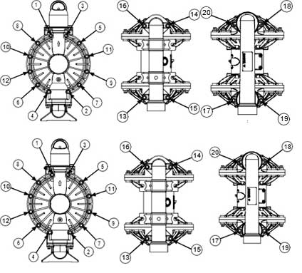
Worn air valve block (7), o-ring (6), plate (8), pilot block (18), u-cups (10), or pilot pin o-rings (17). |
Repair or replace. See pages 13 to 14. |
|
Worn shaft seals (402). |
Replace. See pages 17 to 19. |
|
|
Pump leaks air externally. |
Air valve cover (2) or air valve cover screws (3) are loose. |
Tighten screws. See page 14. |
|
Air valve gasket (4) or air cover gasket (22) is damaged. |
Inspect; replace. See pages 13 to 14, 20 to 21. |
|
|
Air cover screws (3) are loose. |
Tighten screws. See pages 20 to 21. |
|
|
Pump leaks fluid externally from ball check valves. |
Loose manifolds (102, 103), damaged seal between manifold and seat (201), or damaged o-rings (202). |
Tighten manifold bolts (106) or replace seats (201) or o-rings (202). See page 15. |
Service
Repairing the Air Valve
Tools Required
•Torque wrench
•Torx (T20) screwdriver or 7 mm (9/32”) socket wrench
•Needle-nose pliers
•O-ring pick
•Lithium base grease
NOTE: Air Valve Repair Kits 236273 (aluminum center housings) and 255061 (stainless steel center hous- ings) are available. Refer to page 24. Parts included in the kit are marked with a symbol, for example (4†■).
Use all the parts in the kit for the best results.
Disassembly
1.Follow the Pressure Relief Procedure Warning on page 10.
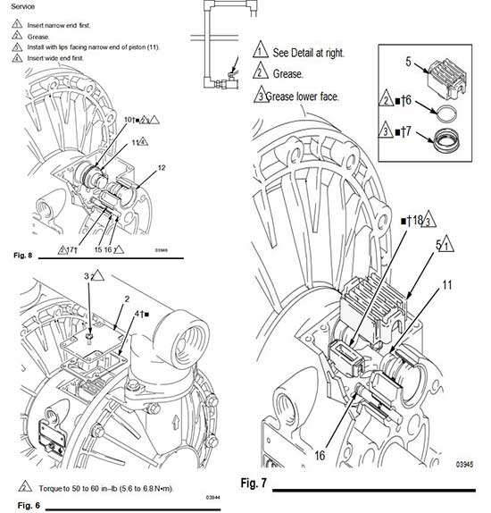
2.With a Torx (T20) screwdriver or 7 mm (9/32”) socket wrench, remove the six screws (3), air valve cover (2), and gasket (4). See Fig. 6.
3.Move the valve carriage (5) to the center position and pull it out of the cavity. Remove the valve block (7) and o-ring (6) from the carriage. Using a needle-nose pliers, pull the pilot block (18) straight up and out of the cavity. See Fig. 7.
4.Pull the two actuator pistons (11) out of the bear- ings (12). Remove the u-cup packings (10) from the pistons. Pull the pilot pins (16) out of the bearings (15). Remove the o-rings (17) from the pilot pins. See Fig. 8.
5.Inspect the valve plate (8) in place. If damaged, use a Torx (T20) screwdriver or 7 mm (9/32”) socket wrench to remove the three screws (3). Remove the valve plate (8) and, on aluminum center housing models only, remove the seal (9). See Fig. 9.
6.Inspect the bearings (12, 15) in place. See Fig. 8. The bearings are tapered and, if damaged, must be removed from the outside. This requires disas- sembly of the fluid section. See page 20.
7.Clean all parts and inspect for wear or damage. Replace as needed. Reassemble as explained on page 14.
Reassembly
1.If you removed the bearings (12, 15), install new ones as explained on page 20. Reassemble the fluid section.
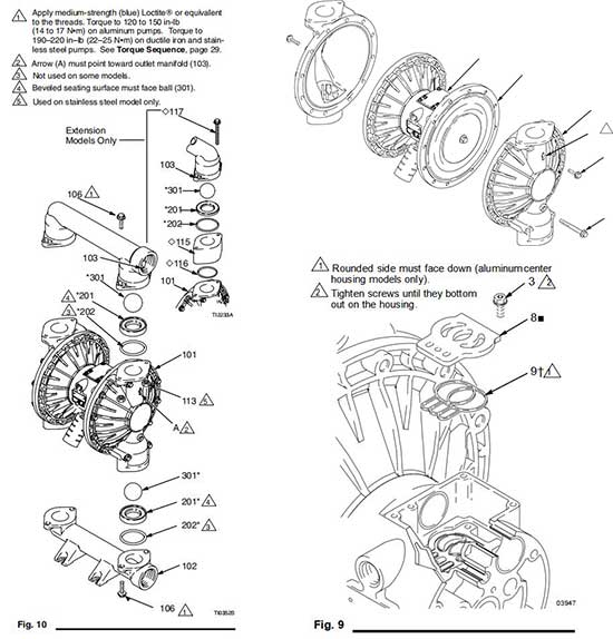
2.On aluminum center housing models, install the valve plate seal (9†) into the groove at the bottom of the valve cavity. The rounded side of the seal must face down into the groove. See Fig. 9.
3.Install the valve plate (8■) in the cavity. On alumi- num center housing models, the plate is reversible, so either side can face up. Install the three screws (3), using a Torx (T20) screwdriver or 7 mm (9/32”) socket wrench. Tighten until the screws bottom out on the housing. See Fig. 9.
4.Install an o-ring (17†■) on each pilot pin (16). Grease the pins and o-rings. Insert the pins into the bearings (15), narrow end first. See Fig. 8.
5.Install a u-cup packing (10†■) on each actuator piston (11), so the lips of the packings face the narrow end of the pistons. See Fig. 8.
6.Lubricate the u-cup packings (10†■) and actuator pistons (11). Insert the actuator pistons in the bearings (12), wide end first. Leave the narrow end of the pistons exposed. See Fig. 8.
7.Grease the lower face of the pilot block (18†■) and install so its tabs snap into the grooves on the ends of the pilot pins (16). See Fig. 7.
8.Grease the o-ring (6†■) and install it in the valve block (7†■). Push the block onto the valve carriage (5). Grease the lower face of the valve block. See Fig. 7.
9.Install the valve carriage (5) so its tabs slip into the grooves on the narrow end of the actuator pistons (11). See Fig. 7.
10.Align the valve gasket (4†■) and cover (2) with the six holes in the center housing (1). Secure with six screws (3), using a Torx (T20) screwdriver or 7 mm (9/32”) socket wrench. Torque to 50 to 60 in-lb (5.6 to 6.8 N•m). See Fig. 6.
Ball Check Valve Repair
Tools Required
•Torque wrench
•10 mm socket wrench
•O-ring pick
Disassembly
NOTE: A Fluid Section Repair Kit is available. Refer to page 23 to order the correct kit for your pump. Parts included in the kit are marked with an asterisk, for example (201*). Use all the parts in the kit for the best results.
NOTE: To ensure proper seating of the balls (301), always replace the seats (201) when replacing the balls.
NOTE: (Extension Version) To ensure proper sealing of extension (115), always replace o–rings (116) when replacing the balls.
1.Follow the Pressure Relief Procedure Warning
on page 10. Disconnect all hoses.
2.Remove the pump from its mounting.
3.Using a 10 mm socket wrench, remove the four bolts (106) holding the outlet manifold (103) to the fluid covers (101). See Fig. 10.
4.Remove the seats (201), balls (301), and o-rings
(202) from the manifold.
NOTE: Some models do not use o-rings (202).
5.Turn the pump over and remove the inlet manifold (102). Remove the seats (201), balls (301), and
o-rings (202) from the fluid covers (101).
Reassembly
1.Clean all parts and inspect for wear or damage. Replace parts as needed.
- Reassemble in the reverse order, following all notes in Fig. 10. Be sure the ball checks are assembled exactly as shown. The arrows (A) on the fluid covers (101) must point toward the outlet manifold (103).
Apply medium-strength (blue) Loctite® or equivalent to the threads. Torque to 120 to 150 in-lb
(14 to 17 N•m) on aluminum pumps. Torque to 190–220 in–lb (22–25 N•m) on ductile iron and stain- less steel pumps. See Torque Sequence, page 29.
Arrow (A) must point toward outlet manifold (103).
Not used on some models.
Beveled seating surface must face ball (301).
Used on stainless steel model only.
Diaphragm Repair
Tools Required
•Torque wrench
•10 mm socket wrench
•13 mm socket wrench
•15 mm socket wrench (aluminum models) or 1” socket wrench (stainless steel models)
•19 mm open–end wrench
•O-ring pick
•Lithium-base grease
1Apply medium-strength (blue) Loctite® or equivalent to the threads. You must torque the eight long screws (112) first, then the short screws (106). Torque to 190 to 220 in-lb (22 to 25 N•m). See Torque
Sequence, page 29.
2Arrow (A) must point toward air valve (B).