

Versa-Matic Diaphragm Pump U2SP5F5S9
Packing and shipping
|
Packaging Regulation : |
Wooden box |
|
Delivery time : |
7~14 days(About) |
|
Conditions : |
New and Genuine |

How do you order?
A&S makes ordering GET Parts easy. Simply send a mail to Us. Instead of searching online and guessing which parts you need, our team will make sure you get the correct parts. We process and deliver your order fast, and always at a competitive price. Enjoy 5-star service!
1.IDENTIFY
Determine the parts you need. To ensure the correct parts are quoted, it's best to have the machine make and model, along with part numbers and photos of the nameplate if possible. Our team of professionals are here to help ensure you get the correct parts that fit and work the first time. Our sales team can also survey and help identify the parts you may need. Please email us to get started!
2.ORDER
Our professional internal sales teams and strong supply chain system will assist you to identify the right parts, and can recommend the most cost-effective solution for you. Our team of professionals will process your order, and ensure your order is correct the first time. With over 15 years in the business, we remove the guesswork and always deliver.
3.DELIVER
We'll ship or deliver your products as required, to your nominated location. If you're also located elsewhere, we'll identify the best shipping options for both price and delivery time. Email us now!
U2SP5F5S9-258882
2" Ultra-Matic Bolted
with Metallic Center Section
U2 Metallic Pumps
•Stainless Steel
•Hastelloy C
•Cast Iron
IMPORTANT
Read the safety warnings and instructions in this manual before pump installation and start-up. Failure to comply with the recommendations stated in this manual could damage the pump and void factory warranty.
When the pump is used for materials that tend to settle out or solidify, the pump should be flushed after each use to
prevent damage. In freezing temperatures the pump should be completely drained between uses.
CAUTION
Before pump operation, inspect all fasteners for loosening caused by gasket creep. Retighten loose fasteners to prevent leakage. Follow recommended torques stated in this manual.
Nonmetallic pumps and plastic components are not UV stabilized. Ultraviolet radiation can damage these parts and negatively affect material properties. Do not expose to UV light for extended periods of time.
WARNING
Pump not designed, tested or certified to be powered by compressed natural gas. Powering the pump with natural gas will void the warranty.
WARNING
When used for toxic or aggressive fluids, the pump should always be flushed clean prior to disassembly.
Before maintenance or repair, shut off the compressed air line, bleed the pressure, and disconnect the air line from the pump. Be certain that approved eye protection and protective clothing are worn at all times. Failure to follow these recommendations may result in serious injury or death.
Airborne particles and loud noise hazards. Wear eye and ear protection.
In the event of diaphragm rupture, pumped material may enter the air end of the pump, and be discharged into the atmosphere. If pumping a product that is hazardous or toxic, the air exhaust must be piped to an appropriate area for safe containment.
Take action to prevent static sparking. Fire or explosion can result, especially when handling flammable liquids. The pump, piping, valves, containers and other miscellaneous equipment must be properly grounded.
This pump is pressurized internally with air pressure during operation. Make certain that all fasteners are in good condition and are reinstalled properly during reassembly.
Use safe practices when lifting
Grounding the Pump
To be fully groundable, the pumps must be ATEX Compliant. Refer to the nomenclature page for ordering information.
Optional 8 foot long (244 centimeters) Ground Strap is available for easy ground connection.
To reduce the risk of static electrical sparking, this pump must be grounded. Check the local electrical code for detailed grounding instruction and the type of equipment required.
Refer to nomenclature page for ordering information.
WARNING
Take action to prevent static sparking. Fire or explosion can result, especially when handling flammable liquids. The pump, piping, valves, containers or other miscellaneous equipment must be grounded.
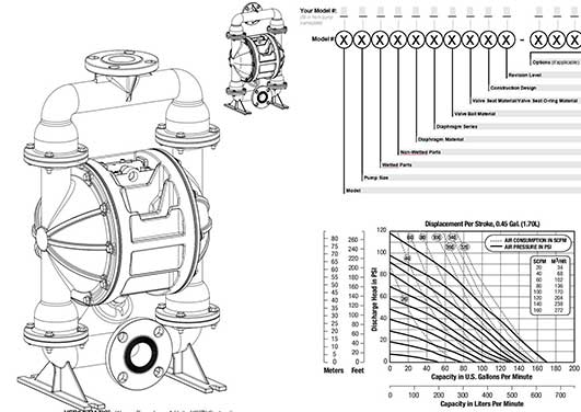
Your Serial #: (fill in from pump nameplate)
Your Model #:
(fill in from pump nameplate)
|
Model E Elima-Matic U Ultra-Matic V V-Series |
Pump Size 6 1/4" 8 3/8" 5 1/2" |
Wetted Parts A Aluminum C Cast Iron S Stainless Steel |
Non-Wetted Parts A Aluminum S Stainless Steel P Polypropylene |
Diaphragm Material 1 Neoprene 2 Nitrile (Nitrile) 3 FKM (Fluorocarbon) |
|
RE AirVantage |
7 3/4" 1 1" 4 1-1/4" or 1-1/2" 2 2" 3 3" |
H Alloy C P Polypropylene K Kynar G Groundable Acetal B Aluminum (screen mount) |
G Groundable Acetal Z PTFE-coated Aluminum J Nickel-plated Aluminum C Cast Iron Q Epoxy-Coated Aluminum |
4 EPDM 5 PTFE 6 Santoprene XL 7 Hytrel 9 Geolast |
|
Diaphragm Series R Rugged D Dome X Thermo-Matic T Tef-Matic (2-piece) B Versa-Tuff (1-piece) F FUSION (one-piece integrated plate) |
Valve Ball Material Valve 1 Neoprene 2 Nitrile 3 (FKM) Fluorocarbon 4 EPDM 5 PTFE 6 Santoprene XL 7 Hytrel 8 Polyurethane 9 Geolast A Acetal S Stainless Steel |
Seat/Valve Seat O-Ring Material 1 Neoprene 2 Nitrile 3 (FKM) Fluorocarbon 4 EPDM 5 PTFE 6 Santoprene XL 7 Hytrel 8 Polyurethane 9 Geolast A Aluminum w/ PTFE O-Rings S Stainless Steel w/ PTFE O-Rings C Carbon Steel w/ PTFE O-Rings H Alloy C w/ PTFE O-Rings |
Construction Design 9 Bolted 0 Clamped |
|
Materials
|
Material Profile: CAUTION! Operating temperature limitations are as follows: Conductive Acetal: Tough, impact resistant, ductile. Good abrasion resistance and low friction surface. Generally inert, with good chemical resistance except for strong acids and oxidizing agents. |
Operating Temperatures: |
|
|
Max. |
Min. |
|
|
190°F 88°C |
-20°F -29°C |
|
|
EPDM: Shows very good water and chemical resistance. Has poor resistance to oils and solvents, but is fair in ketones and alcohols. |
280°F 138°C |
-40°F -40°C |
|
FKM: (Fluorocarbon) Shows good resistance to a wide range of oils and sovents; especially all aliphatic, aromatic and halogenated hydrocarbons, acids, animal and vegetable oils. Hot water or hot aqueous solutions (over 70°F) will attack FKM. |
350°F 177°C |
-40°F -40°C |
|
Hytrel®: Good on acids, bases, amines and glycols at room temperatures only. |
220°F 104°C |
-20°F -29°C |
|
Neoprene: All purpose. Resistance to vegetable oils. Generally not affected by moderate chemicals, fats, greases and many oils and solvents. Generally attacked by strong oxidizing acids, ketones, esters and nitro hydrocarbons and chlorinated aromatic hydrocarbons. |
200°F 93°C |
-10°F -23°C |
|
Nitrile: General purpose, oil-resistant. Shows good solvent, oil, water and hydraulic fluid resistance. Should not be used with highly polar solvents like acetone and MEK, ozone, chlorinated hydrocarbons and nitro hydrocarbons. |
190°F 88°C |
-10°F -23°C |
|
Nylon: 6/6 High strength and toughness over a wide temperature range. Moderate to good resistance to fuels, oils and chemicals. |
180°F 82°C |
32°F 0°C |
|
Polypropylene: A thermoplastic polymer. Moderate tensile and flex strength. Resists stong acids and alkali. Attacked by chlorine, fuming nitric acid and other strong oxidizing agents. |
180°F 82°C |
32°F 0°C |
|
PVDF: (Polyvinylidene Fluoride) A durable fluoroplastic with excellent chemical resistance. Excellent for UV applications. High tensile strength and impact resistance. |
250°F 121°C |
0°F -18°C |
|
Santoprene®: Injection molded thermoplastic elastomer with no fabric layer. Long mechanical flex life. Excellent abrasion resistance. |
275°F 135°C |
-40°F -40°C |
|
UHMW PE: A thermoplastic that is highly resistant to a broad range of chemicals. Exhibits outstanding abrasion and impact resistance, along with environmental stress-cracking resistance. |
180°F 82°C |
-35°F -37°C |
|
Urethane: Shows good resistance to abrasives. Has poor resistance to most solvents and oils. |
150°F 66°C |
32°F 0°C |
|
Virgin PTFE: (PFA/TFE) Chemically inert, virtually impervious. Very few chemicals are known to chemically react with PTFE; molten alkali metals, turbulent liquid or gaseous fluorine and a few fluoro-chemicals such as chlorine trifluoride or oxygen difluoride which readily liberate free fluorine at elevated temperatures. |
220°F 104°C |
-35°F -37°C |
|
Maximum and Minimum Temperatures are the limits for which these materials can be operated. Temperatures coupled with pressure affect the longevity of diaphragm pump components. Maximum life should not be expected at the extreme limits of the temperature ranges. |
||
|
Metals: |
||
|
Alloy C: Equal to ASTM494 CW-12M-1 specification for nickel and nickel alloy. |
||
|
Stainless Steel: Equal to or exceeding ASTM specification A743 CF-8M for corrosion resistant iron chromium, iron chromium nickel and nickel based alloy castings for general applicaitons. Commonly referred to as 316 Stainless Steel in the pump industry. |
||
Performance
U2 - 2” Bolted Metallic Pump
Vertical Discharge
Flow Rate
Adjustable to .. 0-170 gpm (644 lpm)
Port Size
Suction 2" ANSI/DIN #50 Flange
Discharge 2" ANSI/DIN #50 Flange
Air Inlet 1/2" NPT
Air Exhaust 3/4" NPT
Suction Lift (Dry)
Rubber 20' (6.10 m)
PTFE 10' (3.05 m)
Max Solid Size (Diameter)
...................... 7/16" (11.1 mm)
Shipping Weights
Cast Iron 115 lbs (52 kg)
Hastelloy C 123 lbs (56 kg)
Stainless Steel 115 lbs (52 kg)
NOTE: Performance based on the following: elastomeric fitted pump, flooded suction, water at ambient conditions. The use of other materials and varying hydraulic conditions may result in deviations in excess of 5%.
NOTE:For U2 pumps fitted with PTFE diaphragms, reduce water discharge figures by 20%.Suction lift is reduced to 10' (3.05m) dry and 20' (6.10m) wet.
CAUTION: Do not exceed 125 psig (8.5 bars) air supply or liquid pressure.
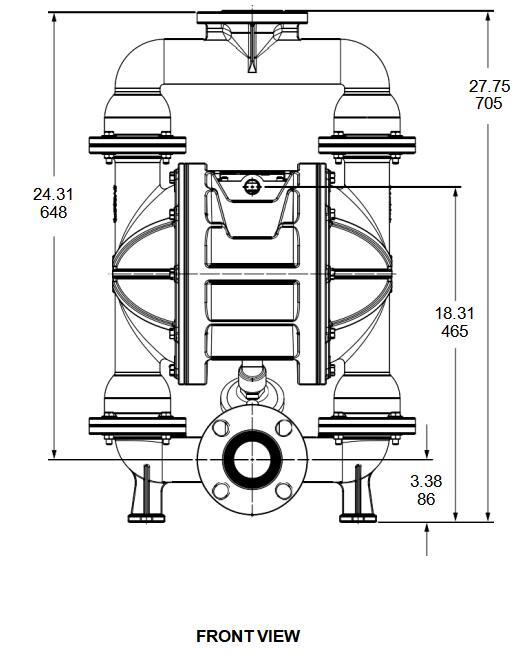
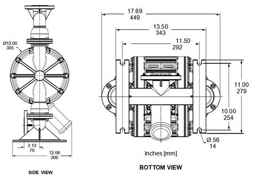
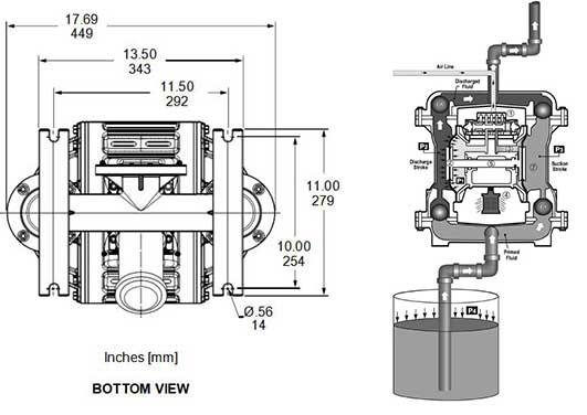
dimensional drawings
U2 Metallic Bolted - Vertical Discharge
Dimensions in inches (mm dimensions in brackets)
The dimensions on this drawing are for reference only. A certified drawing can be requested if physical dimensions are needed.
FRONT VIEW
SIDE VIEW
BOTTOM VIEW
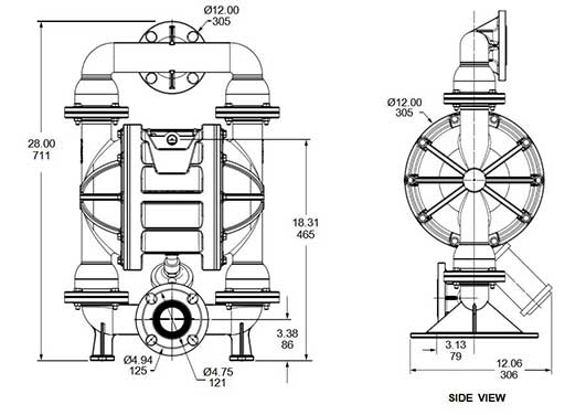
dimensional drawings
U2 Metallic Bolted - Horizontal Discharge
Dimensions in inches (mm dimensions in brackets)
The dimensions on this drawing are for reference only. A certified drawing can be requested if physical dimensions are needed.
FRONT VIEW
FRONT VIEW
FRONT VIEW
Principle of Pump Operation
Air-Operated Double Diaphragm (AODD) pumps are powered by compressed air or nitrogen.
The main directional (air) control valve ① distributes compressed air to an air chamber, exerting uniform pressure over the inner surface of the diaphragm ②. At the same time, the exhausting air ③ from behind the opposite diaphragm is directed through the air valve assembly(s) to an exhaust port ④.
As inner chamber pressure (P1) exceeds liquid chamber pressure (P2), the rod ⑤ connected diaphragms shift together creating discharge on one side and suction on the opposite side. The discharged and primed liquid’s directions are controlled by the check valves (ball or flap)⑥ orientation.
The pump primes as a result of the suction stroke. The suction stroke lowers the chamber pressure (P3) increasing the chamber volume. This results in a pressure differential necessary for atmospheric pressure (P4) to push the fluid through the suction piping and across the suction side check valve and into the outer fluid chamber ⑦.
Suction (side) stroking also initiates the reciprocating (shifting, stroking or cycling) action of the pump. The suction diaphragm’s movement is mechanically pulled through its stroke. The diaphragm’s inner plate makes contact with an actuator plunger aligned to shift the pilot signaling valve. Once actuated, the pilot valve sends a pressure signal to the opposite end of the main directional air valve, redirecting the compressed air to the opposite inner chamber.
SUBMERGED ILLUSTRATION
Pump can be submerged if the pump materials of construction are compatible with the liquid being pumped. The air exhaust must be piped above the liquid level. When the pumped product source is at a higher level than the pump (flooded suction condition), pipe the exhaust higher than the product source to prevent siphoning spills.
recommended Installation Guide
Available Accessories:
1.Surge Suppressor
2.Filter/Regulator
3.Air Dryer
Installation And Start-Up
Locate the pump as close to the product being pumped as possible. Keep the suction line length and number of fittings to a minimum. Do not reduce the suction line diameter.
Air Supply
Connect the pump air inlet to an air supply with sufficient capacity and pressure to achieve desired performance. A pressure regulating valve should be installed to insure air supply pressure does not exceed recommended limits.
Air Valve Lubrication
The air distribution system is designed to operate WITHOUT lubrication. This is the standard mode of operation. If lubrication is desired, install an air line lubricator set to deliver one drop of SAE 10 non-detergent oil for every 20 SCFM (9.4 liters/sec.) of air the pump consumes. Consult the Performance Curve to determine air consumption.
Air Line Moisture
Water in the compressed air supply may cause icing or freezing of the exhaust air, causing the pump to cycle erratically or stop operating. Water in the air supply can be reduced by using a point-of-use air dryer.
Air Inlet And Priming
To start the pump, slightly open the air shut-off valve. After the pump primes, the air valve can be opened to increase air flow as desired. If opening the valve increases cycling rate, but does not increase the rate of flow, cavitation has occurred. The valve should be closed slightly to obtain the most efficient air flow to pump flow ratio.
Troubleshooting Guide
|
Symptom: Potential Cause(s): Recommendation(s): |
||
|
Pump Cycles Once |
Deadhead (system pressure meets or exceeds air supply pressure). |
Increase the inlet air pressure to the pump. Pump is designed for 1:1 pressure ratio at zero flow. (Does not apply to high pressure 2:1 units). |
|
Air valve or intermediate gaskets installed incorrectly. |
Install gaskets with holes properly aligned. |
|
|
Bent or missing actuator plunger. |
Remove pilot valve and inspect actuator plungers. |
|
|
Pump Will Not Operate / Cycle |
Pump is over lubricated. |
Set lubricator on lowest possible setting or remove. Units are designed for lube free operation. |
|
Lack of air (line size, PSI, CFM). |
Check the air line size and length, compressor capacity (HP vs. cfm required). |
|
|
Check air distribution system. |
Disassemble and inspect main air distribution valve, pilot valve and pilot valve actuators. |
|
|
Discharge line is blocked or clogged manifolds. |
Check for inadvertently closed discharge line valves. Clean discharge manifolds/piping. |
|
|
Deadhead (system pressure meets or exceeds air supply pressure). |
Increase the inlet air pressure to the pump. Pump is designed for 1:1 pressure ratio at zero flow. (Does not apply to high pressure 2:1 units). |
|
|
Blocked air exhaust muffler. |
Remove muffler screen, clean or de-ice, and re-install. |
|
|
Pumped fluid in air exhaust muffler. |
Disassemble pump chambers. Inspect for diaphragm rupture or loose diaphragm plate assembly. |
|
|
Pump chamber is blocked. |
Disassemble and inspect wetted chambers. Remove or flush any obstructions. |
|
|
Pump Cycles and Will Not Prime or No Flow |
Cavitation on suction side. |
Check suction condition (move pump closer to product). |
|
Check valve obstructed. Valve ball(s) not seating properly or sticking. |
Disassemble the wet end of the pump and manually dislodge obstruction in the check valve pocket. Clean out around valve ball cage and valve seat area. Replace valve ball or valve seat if damaged. Use heavier valve ball material. |
|
|
Valve ball(s) missing (pushed into chamber or manifold). |
Worn valve ball or valve seat. Worn fingers in valve ball cage (replace part). Check Chemical Resistance Guide for compatibility. |
|
|
Valve ball(s)/seat(s) damaged or attacked by product. |
Check Chemical Resistance Guide for compatibility. |
|
|
Check valve and/or seat is worn or needs adjusting. |
Inspect check valves and seats for wear and proper setting. Replace if necessary. |
|
|
Suction line is blocked. |
Remove or flush obstruction. Check and clear all suction screens or strainers. |
|
|
Excessive suction lift. |
For lifts exceeding 20’ of liquid, filling the chambers with liquid will prime the pump in most cases. |
|
|
Suction side air leakage or air in product. |
Visually inspect all suction-side gaskets and pipe connections. |
|
|
Pumped fluid in air exhaust muffler. |
Disassemble pump chambers. Inspect for diaphragm rupture or loose diaphragm plate assembly. |
|
|
Pump Cycles Running Sluggish/Stalling, Flow Unsatisfactory |
Over lubrication. |
Set lubricator on lowest possible setting or remove. Units are designed for lube free operation. |
|
Icing. |
Remove muffler screen, de-ice, and re-install. Install a point of use air drier. |
|
|
Clogged manifolds. |
Clean manifolds to allow proper air flow |
|
|
Deadhead (system pressure meets or exceeds air supply pressure). |
Increase the inlet air pressure to the pump. Pump is designed for 1:1 pressure ratio at zero flow. (Does not apply to high pressure 2:1 units). |
|
|
Cavitation on suction side. |
Check suction (move pump closer to product). |
|
|
Lack of air (line size, PSI, CFM). |
Check the air line size, length, compressor capacity. |
|
|
Excessive suction lift. |
For lifts exceeding 20’ of liquid, filling the chambers with liquid will prime the pump in most cases. |
|
|
Air supply pressure or volume exceeds system hd. |
Decrease inlet air (press. and vol.) to the pump. Pump is cavitating the fluid by fast cycling. |
|
|
Undersized suction line. |
Meet or exceed pump connections. |
|
|
Restrictive or undersized air line. |
Install a larger air line and connection. |
|
|
Suction side air leakage or air in product. |
Visually inspect all suction-side gaskets and pipe connections. |
|
|
Suction line is blocked. |
Remove or flush obstruction. Check and clear all suction screens or strainers. |
|
|
Pumped fluid in air exhaust muffler. |
Disassemble pump chambers. Inspect for diaphragm rupture or loose diaphragm plate assembly. |
|
|
Check valve obstructed. |
Disassemble the wet end of the pump and manually dislodge obstruction in the check valve pocket. |
|
|
Check valve and/or seat is worn or needs adjusting. |
Inspect check valves and seats for wear and proper setting. Replace if necessary. |
|
|
Entrained air or vapor lock in chamber(s). |
Purge chambers through tapped chamber vent plugs. Purging the chambers of air can be dangerous. |
|
|
Product Leaking Through Exhaust |
Diaphragm failure, or diaphragm plates loose. |
Replace diaphragms, check for damage and ensure diaphragm plates are tight. |
|
Diaphragm stretched around center hole or bolt holes. |
Check for excessive inlet pressure or air pressure. Consult Chemical Resistance Chart for compatibility with products, cleaners, temperature limitations and lubrication. |
|
|
Premature Diaphragm Failure |
Cavitation. |
Enlarge pipe diameter on suction side of pump. |
|
Excessive flooded suction pressure. |
Move pump closer to product. Raise pump/place pump on top of tank to reduce inlet pressure. Install Back pressure device (Tech bulletin 41r). Add accumulation tank or pulsation dampener. |
|
|
Misapplication (chemical/physical incompatibility). |
Consult Chemical Resistance Chart for compatibility with products, cleaners, temperature limitations and lubrication. |
|
|
Incorrect diaphragm plates or plates on backwards, installed incorrectly or worn. |
Check Operating Manual to check for correct part and installation. Ensure outer plates have not been worn to a sharp edge. |
|
|
Unbalanced Cycling |
Excessive suction lift. |
For lifts exceeding 20’ of liquid, filling the chambers with liquid will prime the pump in most cases. |
|
Undersized suction line. |
Meet or exceed pump connections. |
|
|
Pumped fluid in air exhaust muffler. |
Disassemble pump chambers. Inspect for diaphragm rupture or loose diaphragm plate assembly. |
|
|
Suction side air leakage or air in product. |
Visually inspect all suction-side gaskets and pipe connections. |
|
|
Check valve obstructed. |
Disassemble the wet end of the pump and manually dislodge obstruction in the check valve pocket. |
|
|
Check valve and/or seat is worn or needs adjusting. |
Inspect check valves and seats for wear and proper setting. Replace if necessary. |
|
|
Entrained air or vapor lock in chamber(s). |
Purge chambers through tapped chamber vent plugs. |
|
Composite repair Parts list
|
AIR VALVE ASSEMBLY |
|||
|
Item |
Description |
Qty Standard: Polypropylene |
|
|
|
Air Valve Assembly (Includes items 1-10) |
1 E200 |
|
|
1 |
Valve Body |
1 E200A |
|
|
2 |
Valve Spool Assembly |
1 E200B ASY (Includes U-Cups) |
|
|
3 |
Valve Spool U-Cup |
2 P98-104A |
|
|
4 |
End Cap Assembly |
2 E500D ASY (Includes O-Rings) |
|
|
5 |
End Cap Staple |
2 E500F |
|
|
6 |
Staple Retainer |
2 E200L |
|
|
7 |
Air Diverter |
1 E200G |
|
|
8 |
Valve Insert |
1 E200H |
|
|
9 |
Valve Gasket |
1 E200J |
|
|
10 |
Valve Cap Screw |
4 P24-209 |
|
|
AIR END ASSEMBLY |
|||
|
Item |
Description |
Qty Standard: Polypropylene/Aluminum |
|
|
15 |
Center Section |
1 E201B |
|
|
16 |
Bushing |
2 E201MB |
|
|
17 |
Pilot Shaft |
1 E203A |
|
|
18 |
Pilot Shaft Spacer |
5 P24-106P |
|
|
19 |
Pilot Shaft O-Ring |
6 P24-107 |
|
|
20 |
Stop Nut |
2 P24-108 |
|
|
21 |
Shaft Retainer – Left |
1 E201B-L ASY (Includes O-Rings) |
|
|
22 |
Shaft Retainer – Right (not shown) |
1 E201B-R ASY (Includes O-Rings) |
|
|
23 |
Exhaust Sleeve O-Ring |
2 560.013.360 |
|
|
24 |
Shaft Retainer Screw |
2 10-050 |
|
|
25 |
Exhaust Valve |
2 E202 ASY |
|
|
26 |
Shaft Retainer O-Ring |
2 E201B-5 |
|
|
27 |
Retainer Plate Seal |
2 P34-403 |
|
|
28 |
Muffler Plate |
1 E201H |
|
|
29 |
Muffler Plate Gasket |
1 E200J-1 |
|
|
30 |
Muffler Plate Cap Screw |
4 E201G |
|
|
31 |
Muffler Elbow |
1 PE201N |
|
|
32 |
Muffler |
1 V20AEM |
|
|
DIAPHRAGM ASSEMBLY |
|||
|
Item |
Description |
Qty DOME PTFE Bonded |
PTFE 2-Piece |
|
40 |
Main Shaft |
1 P24-103 P24-102 |
P24-102 |
|
42 |
Inner Diaphragm Plate |
2 V226B SV226B V221T SV221TI V226BTC V226BNP V221TITC V221TINP |
V221TI SV221TI V221TITC V221TINP |
|
43 |
Outer Diaphragm Plate |
2 SVB226 HV226B SV221TO HV221TO |
SV221TO HV221TO |
|
45 |
Diaphragm |
2 V227BN V227N V227ND V227TX V227VT V227TPEXL V227TPEFG |
V227 |
|
46 |
Back-up Diaphragm |
2 N/A N/A |
V227TFB |
|
WET END ASSEMBLY |
|||
|
Item |
Description |
Qty Stnd: Stainless Option 1: Cast Iron |
Option 2: Hastelloy |
|
50 |
Water Chamber |
2 SV235FB WV235FB |
HV235FB |
|
51 |
Water Chamber Bolt |
12 SV185A SV185A |
SV185A |
|
52 |
Water Chamber Washer |
20 SV189C SV189C |
SV189C |
|
53 |
Valve Seat |
4 V240BN V240CS V240N V240ND V240TF V240TPEFG V240TPEXL V240VT SV240 HV240 |
|
|
54 |
Valve Seat O-Ring (not shown) |
8 V240T (USE WITH V240CS, SV240 AND HV240 SEATS) |
|
|
55 |
Valve Ball |
4 V241BN V241N V241ND V241P V241TF V241TPEXL V241TPEFG V241VT |
|
|
Port Option 1: Vertical Discharge |
|||
|
56 |
Discharge Manifold |
1 SV236FB WV236FB |
N/A |
|
57 |
Inlet Manifold |
1 SV237FB N/A |
N/A |
|
58 |
Manifold Bolt |
16 SV189D N/A |
N/A |
|
59 |
Manifold Washer |
16 SV189C N/A |
N/A |
|
60 |
Manifold Nut |
16 SV185B N/A |
N/A |
|
Port Option 2: Horizontal |
|||
|
61 |
Discharge Manifold |
1 SV236F-BH SV236FB-H |
HV236FB-H |
|
62 |
Inlet Manifold |
1 SV237FB-H WV237FB-H |
HV237FB-H |
|
63 |
Manifold Bolt |
16 SV189D SV189D |
SV189D |
|
64 |
Manifold Washer |
16 SV189C SV189C |
SV189C |
|
65 |
Manifold Nut |
16 SV185B SV185B |
SV185B |
Composite repair Parts drawing
|
Torque Settings |
|
|
Manifold Bolts |
25 ft-lbs (34 N-m) |
|
Water Chamber Bolts |
25 ft-lbs (34 N-m) |
|
Diaphragm Plates — Rubber |
65 ft-lbs (88 N-m) |
|
Diaphragm Plates — PTFE |
65 ft-lbs (88 N-m) |
|
Air Valve Cap Screws |
25 in-lbs (2.8 N-m) |
|
Muffler Plate Cap Screws |
30 in-lbs (3.4 N-m) |
Composite repair Parts drawing - detail Views
Composite repair & maintenance Kits
|
AIR VALVE KIT: U2 AV KIT |
||
|
Part # |
Description |
Qty. |
|
P98-104A |
Valve Spool O-Ring |
2 |
|
E200J |
Valve Gasket |
1 |
|
E200G |
Air Diverter |
1 |
|
E200H |
Valve Insert |
1 |
written warranty
5 - yEar limited Product warranty
Quality System ISO9001 Certified • Environmental Management Systems ISO14001 Certified Versa-Matic warrants to the original end-use purchaser that no product sold by Versa-Matic that bears a Versa-Matic brand shall fail under normal use and service due to a defect in material or workmanship within five years from the date of shipment from Versa-Matic’s factory.